Adding 4 more 2.5GbE interfaces to the GMKtec NucBox G9
TL;DR: I added 4x Intel I226-V 2.5GbE network cards to my NucBox G9. You can do it too. Download the files and print them yourself.↗
Backstory
A few months ago, I blogged about using an Intel n150 based mini PC as my home router running OpenWrt. Since then, I’m happy to report that it has been perfectly reliable1.
However, the NucBox G9 runs notoriously hot↗ with NVMe drives installed. Even without any hot NVMe drives installed, I’d describe the overall thermal situation as “not great, not terrible”. I haven’t had any specific issues since OpenWrt is about as light of a load as I could possibly run on it. My unit stays at about 50°C, which is wonderful. What worried me is the 64GB of onboard eMMC storage.
As far as I understand, eMMC is almost exactly a glorified SD card soldered to the board. And if my experience with SD cards, specifically my experience booting computers off of them, is any indication, it would not be very reliable. Adding to my fear was one user’s experience of the eMMC failing after 6 months. Of course I could always boot it off an NVMe or SATA m.2 SSD, or even a USB stick. But the router is the main artery of my entire network and trying to scramble downloading and flashing an OS while my network is down sounds like a horror story I’d like to avoid.
The NucBox is also a victim of its own success for me too. I really love it and it is perfect for my home router. The issue is that these mini PC manufacturers have an approximately 2-week product lifecycle and the G9 is over a year old at this point. In other words - it’s ancient history. There were a handful available on eBay back in May when I first purchased it, but since then the supply has completely dried up. There are replacement models available but thanks to the RAMpocalypse, the prices are outrageous and none of them are an exact drop in replacement for the N150 G9 and it’s Intel NICs.
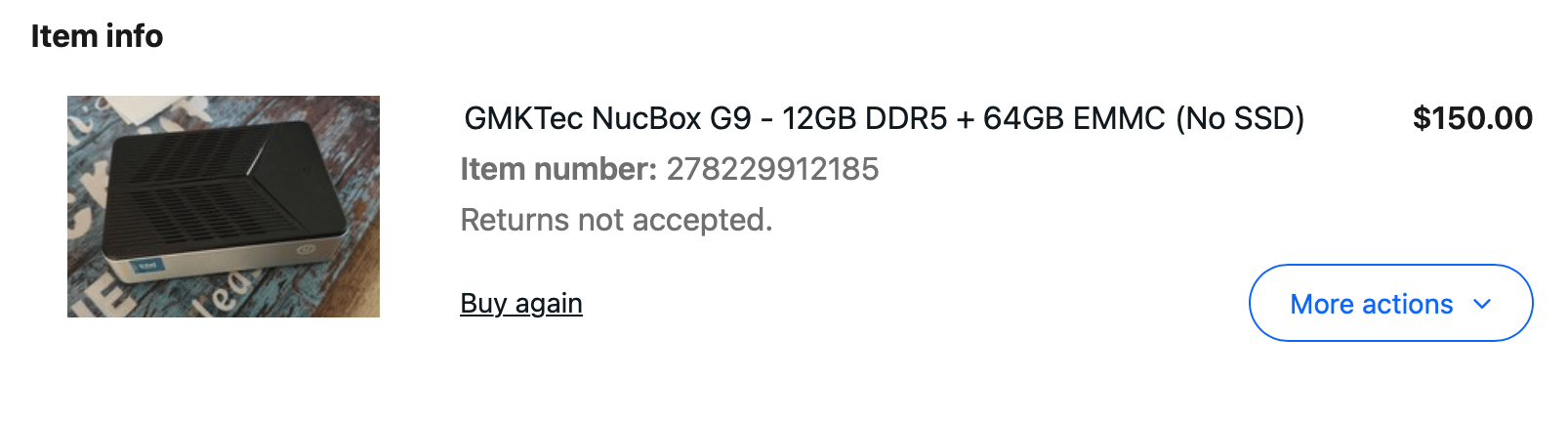
I decided to try and get ahead of any potential hardware failures and procure a spare G9. I set up an eBay alert and mostly forgot about it. One morning I woke up to an email saying a G9 had been listed for $150 buy it now with free shipping. Even less than the $180 I paid for my original unit! A miracle! Sure, it had been “used”, the seller’s description said they’d been running it as an NVMe NAS but it just wasn’t sustainable, especially now that NVMe drives have also succumbed to the AI apocalypse. For my purposes, it was perfect.
Adding the NICs
Once I had the replacement unit in hand, the first thing I did was guillotine the horrific standards violating USB-C power adapter.
Then, I turned my attention to my dream of adding a few more 2.5GbE NICs to it. Why? As I mentioned previously, redundant ISP connections are something I might possibly do in the future, but if I’m being honest it was mostly just because I thought it would be cool. At $25 a pop with two day shipping, they fell into this extremely dangerous territory where your project becomes a series of impulse purchases and the sunk cost fallacy snowballs with each one. I just thought it would be cool, okay?
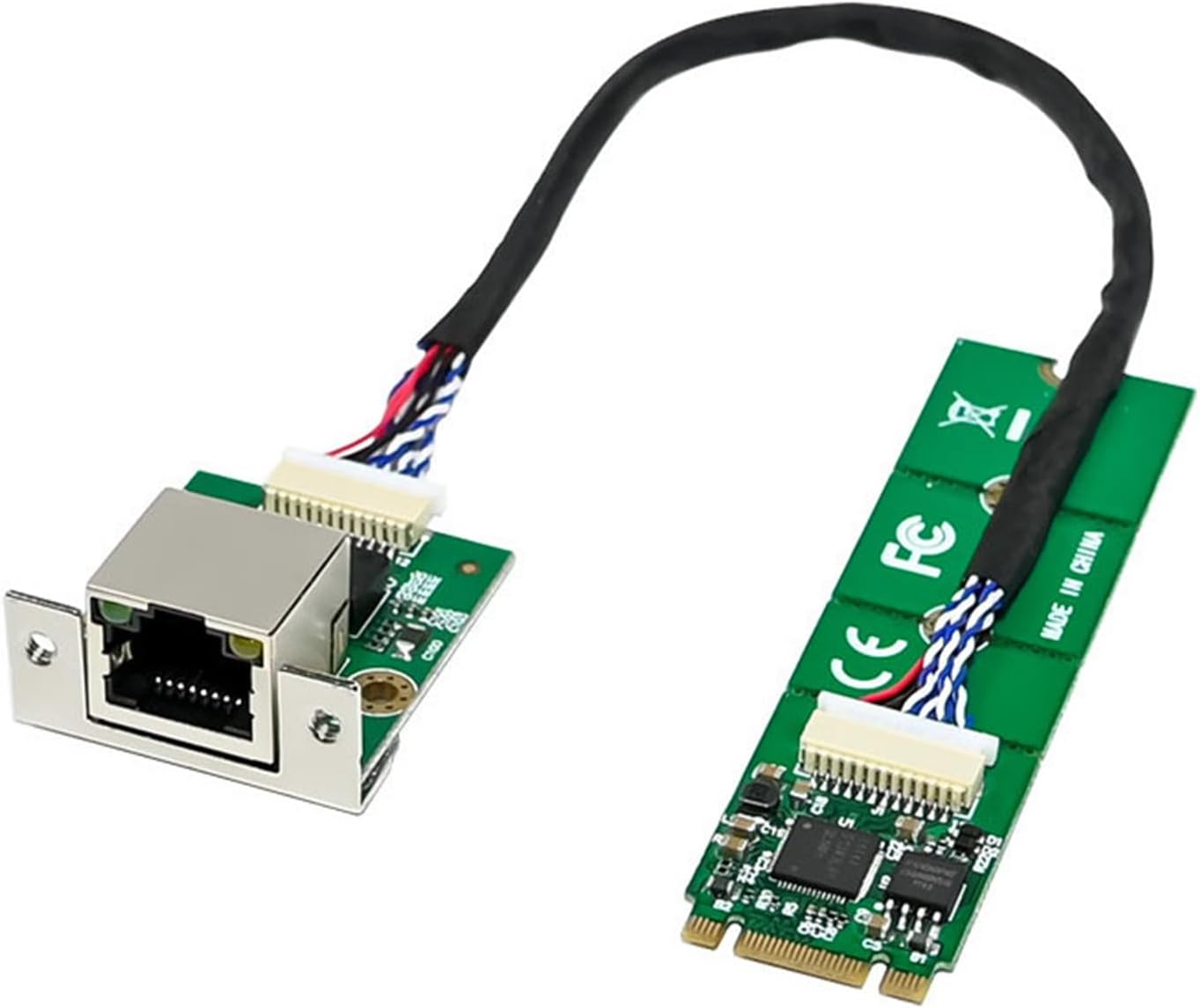
I bought two m.2 B+M key I226-V adapters and plugged them in, ethernet ports dangling off the back. I fired up a fresh copy of Alpine, my Linux of choice, and was pleased to see they “just worked”. I did some rudimentary throughput tests between NICs and was pleased to see I was getting more or less the full 2.5Gb throughput.
The next step was figuring out some kind of mounting solution. My 3D design skills are about a 0.1/10, so the project stopped there for a few weeks. I left everything on my desk, and several times a day I’d just stare at the gear, fiddle with it in my hands, and just kind of wonder about how it all could work.
The G9 is essentially an aluminum center rail with plastic top and bottom plates. The screws are phillips and fully exposed. Very inviting for my iFixit screwdriver kit. The m.2 slots are on the bottom of the kit and that’s the first panel that needs to come off to disassemble the unit. Once I removed the bottom panel, I realized that the geometry was actually fairly simple and some kind of replacement bottom panel wouldn’t be insane to design to bolt on just like the OEM bottom panel. The mounting screws for the m.2 drives are integrated into the OEM bottom panel, which would complicate things, but still, it seemed simple. Yet still out of reach to me. The mere thought of downloading Fusion and logging in fills me with dread.
Claude CAD
Then, one day as I pondered the whole idea some more, I realized surely someone would have designed a bottom shell for it. It’s niche, but the fact that it is all but unusable with the stock bottom case and cooling creates quite a bit of motivation for fellow nerds to do something about it. One google search later, I came to an excellent kit on the Printables site↗ from user “sleeeeeepy”. It did exactly what I had envisioned in my head. A full replacement for the bottom shell with variations for some different fan sizes that would blow directly onto the NVMe drives. It was about 90% of what I needed to realize my dream!
So close, yet still so far. I still wasn’t willing to download Fusion. The print files were distributed as 3MF which is a format I was not familiar with. At work they give me a Claude account so I’ve gotten pretty good at being stupid enough to let it help me with things. Enough so that I reactivated my personal Claude account. So I turned to Claude to give me an idiot’s guide to what a 3MF is. Obviously it’s file format that describes 3D models. I was informed it was literally a zip file with some XML inside, like any good file format is. I mean, if there’s one thing an LLM is good at it’s parsing and creating text files, and at the end of the day XML is just text. So I wondered, could Claude modify the 3D file for me? I had heard not to trust an LLM to do math, and this would be quite a bit of math. I was shocked that it went through it like sliced butter. It burned a lot of tokens as it worked, but it never broke anything. I was measuring things with my digital calipers and feeding dimensions into Claude, working one step at a time through the modifications.
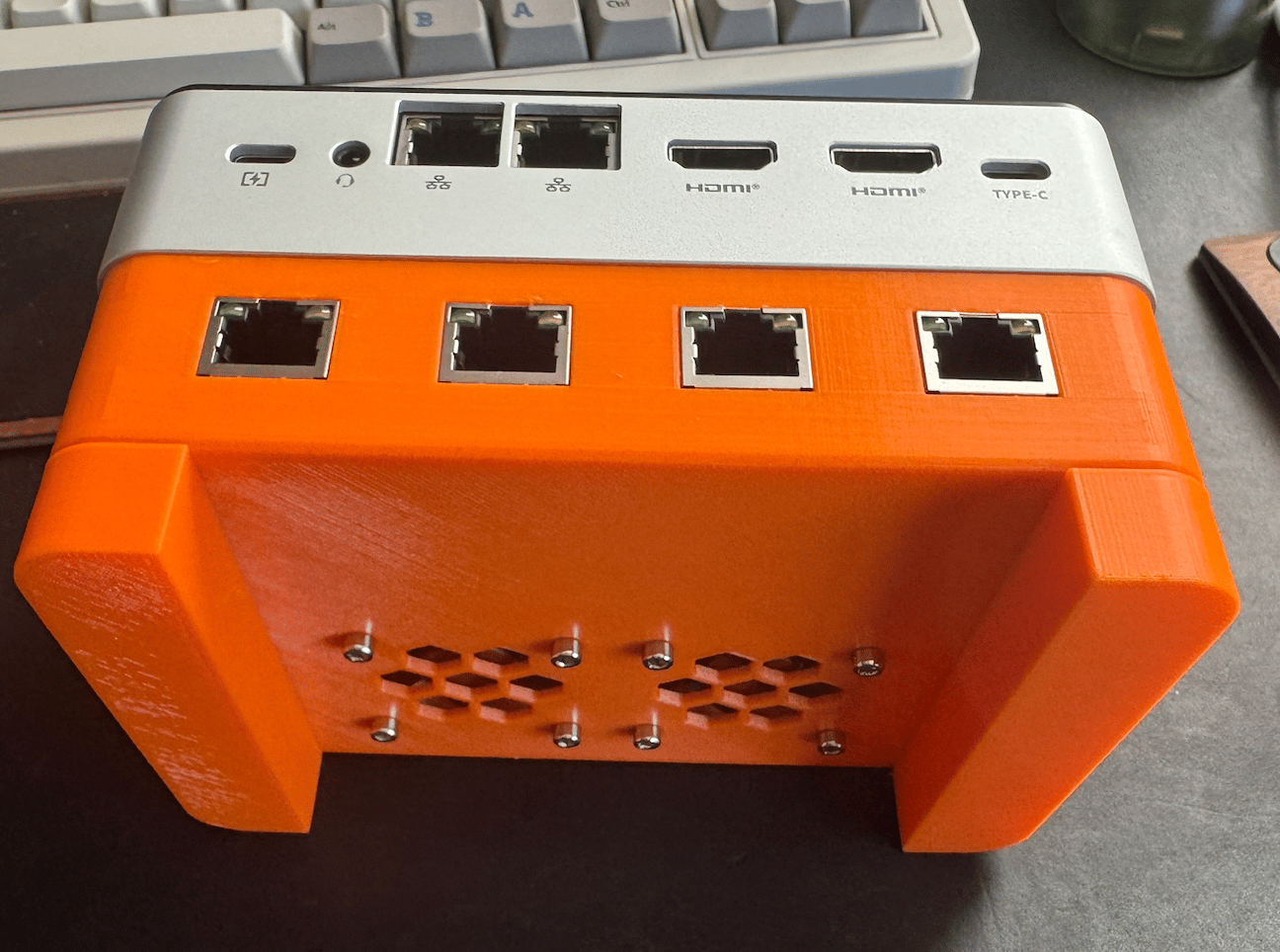
First I added 4 holes for the jacks to sit in. Then I added a mounting rail so I could screw the jack PCBs down with some heat set threaded inserts that are common in 3D print projects. Then I had it add places to mount two 40mm Noctua fans. Once I thought I had it good, I had Claude slice off the front of the shell so I could do a test print to verify the jacks would fit.
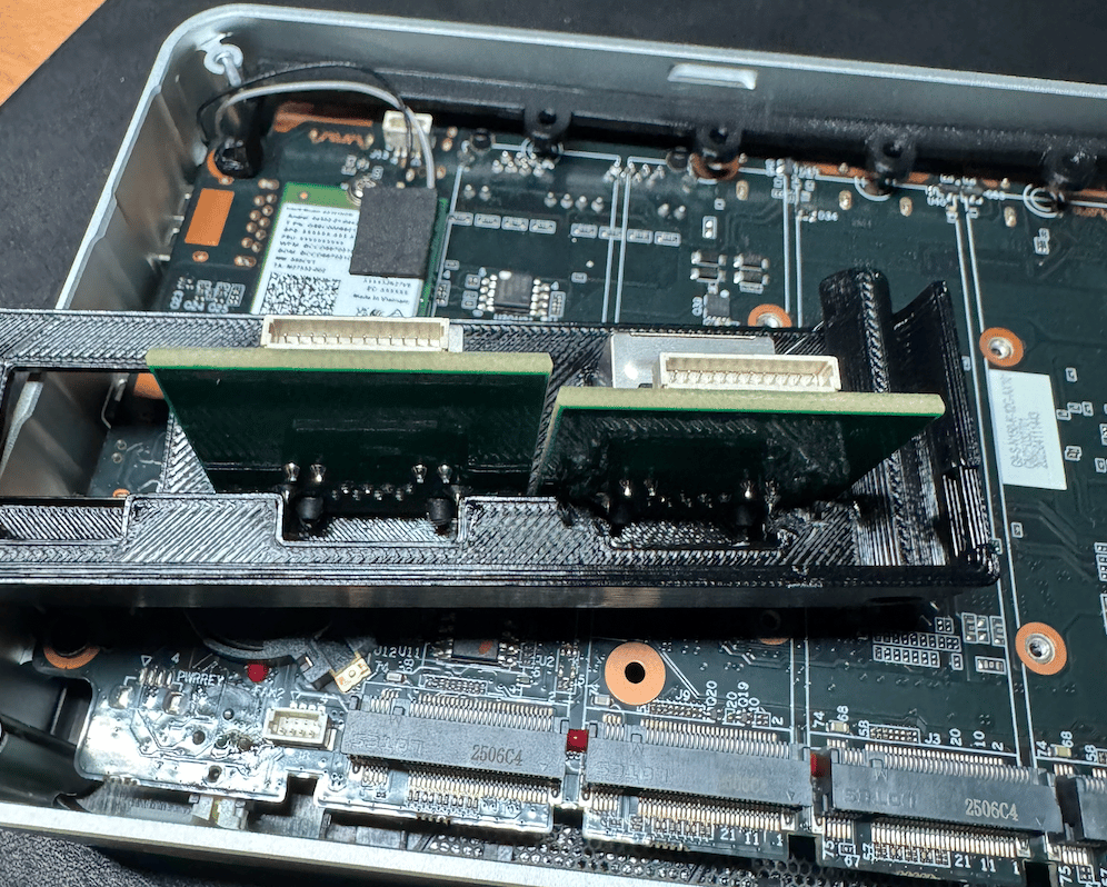
There was a small issue with clearance for some of the through-hole components, so I had Claude redesign to give more clearance. Another test print and it seemed it was totally good to go. A few more impulse purchases sent threaded inserts, fans, and two more NICs my direction.
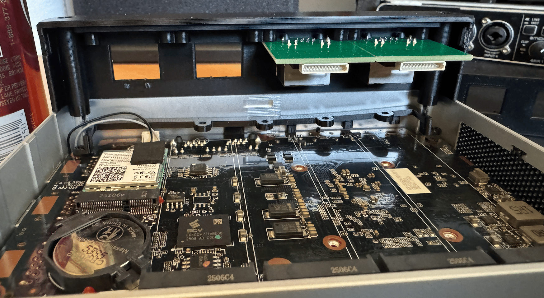
The next day I realized that there probably wasn’t enough clearance to actually get the threaded inserts in place without also melting the front face. That was a simple fix, I had Claude just remove that entire mounting rail from the case so it could be separately printed, inserts added, then glued into place.
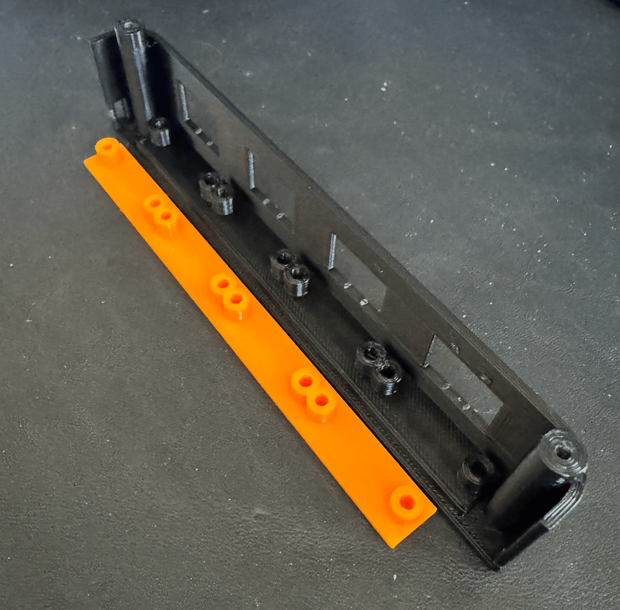
I also switched from PLA to PETG because I hear that PETG will do better long term in hot-ish environments like a computer. Once I verified the mounting rail looked good, I fired off the big print for the bulk of the enclosure. I think it took about 8 hours and I’m not going to publicly admit how many of those hours I spent just staring at the printer do its thing. Am I the only one who is mesmerized by watching a 3D printer print? My kids even joined in for some of it, we stared at it together and it was fun.
Long term Prusa MK3 review
As an aside, due to my extreme lack of 3D modelling skills, my 3D printing journey has been fairly crude. Almost exactly 8 years ago at the time of writing I bought myself a Prusa i3 MK3 kit. It was pretty expensive, I think about $750. At that time I was running Catskull Electronics and had money coming in I needed to reinvest in the business which usually took the form of cool tools I could use to make my life easier as I assembled thousands of circuit boards by hand in my basement. I had purchased a few of the cheap Chinese Creality printers but they never really worked for me. There’s this funny dilemma a lot of 3D printer enthusiasts end up in where the 3D printer becomes the hobby, not so much 3D printing. It makes sense to me, tinkering with a cool machine is a lot more fun than printing kind of poor quality random crap, especially when you don’t have the CAD skills to design anything useful. That was the trap I desperately wanted to escape when I bought the Prusa. Assembly took me nearly a full 10 hours I think, and it printed like absolute garbage. It was mildly devastating. At some point I realized my issue was that the bed was not level enough. I found a simple mod where I could use some nylon locking nuts on the bed screws and an Octoprint plugin to allow me to visualize the level of the bed. Running the plugin gave me a visual map of the hills and valleys on the bed so I could tighten and loosen the nuts to compensate. And once it was dialed in, they should be locked in place and never really move. Once I did that, the 3D printer went from a hobby to a tool. I could just print things, reliably. I did actually get my money’s worth out of it as well. At that time, I was hand assembling surface mount circuit boards with a stainless steel stencil and solder paste. I did them all to order, so very small batches, maybe 3-10 at a time. Normally the way you do this is to tape down a few PCBs around the one you’re going to work on to lock it into place, then you tape down the stencil on top. It’s imprecise and time consuming when you’re just trying to build the things as quickly as you can. I built up enough Fusion skills to print a rectangle with a cutout to match the size of the PCB. I even had rails to hold the stencil in place. I could snap the PCB in place, lay the stencil on top, and my little jig would hold them in place for me to apply the solder paste. As stupid as it sounds, that actually saved me probably hours of time I really didn’t have. Since I stopped doing Catskull Electronics, the Prusa has sat in my closet 99% of the time, only pulling it out maybe once or twice a year when I need some random boring part. I’ve done literally no maintenance to it and I don’t really treat it very gently. It sits in my closet, I pull it out and set it on my floor, print something, then put it back. I don’t even keep the filament in a climate controlled area, but I also live in the desert so humidity is not a problem in the slightest. I keep a spool of black PLA and orange PETG, chosen for no specific reason, both of which are years old at this point and everything still “just works”. So my 8 year review of the Prusa MK3 is to use nylon nuts for the bed, get it level, and then it’s perfect. Whenever I get it out my kids ask me to print them impossible things and it’s hard to explain that it can only really reliably do glorified boxes. I could probably get it to do some more complex geometry if I really wanted to, but I just don’t have the appetite to have a print fail 10 hours in just for some dumb thing you could buy from Amazon for $5 that would be way better quality. It’s only worth it for very custom and simple things like a replacement bottom shell for a NucBox G9!
Final assembly
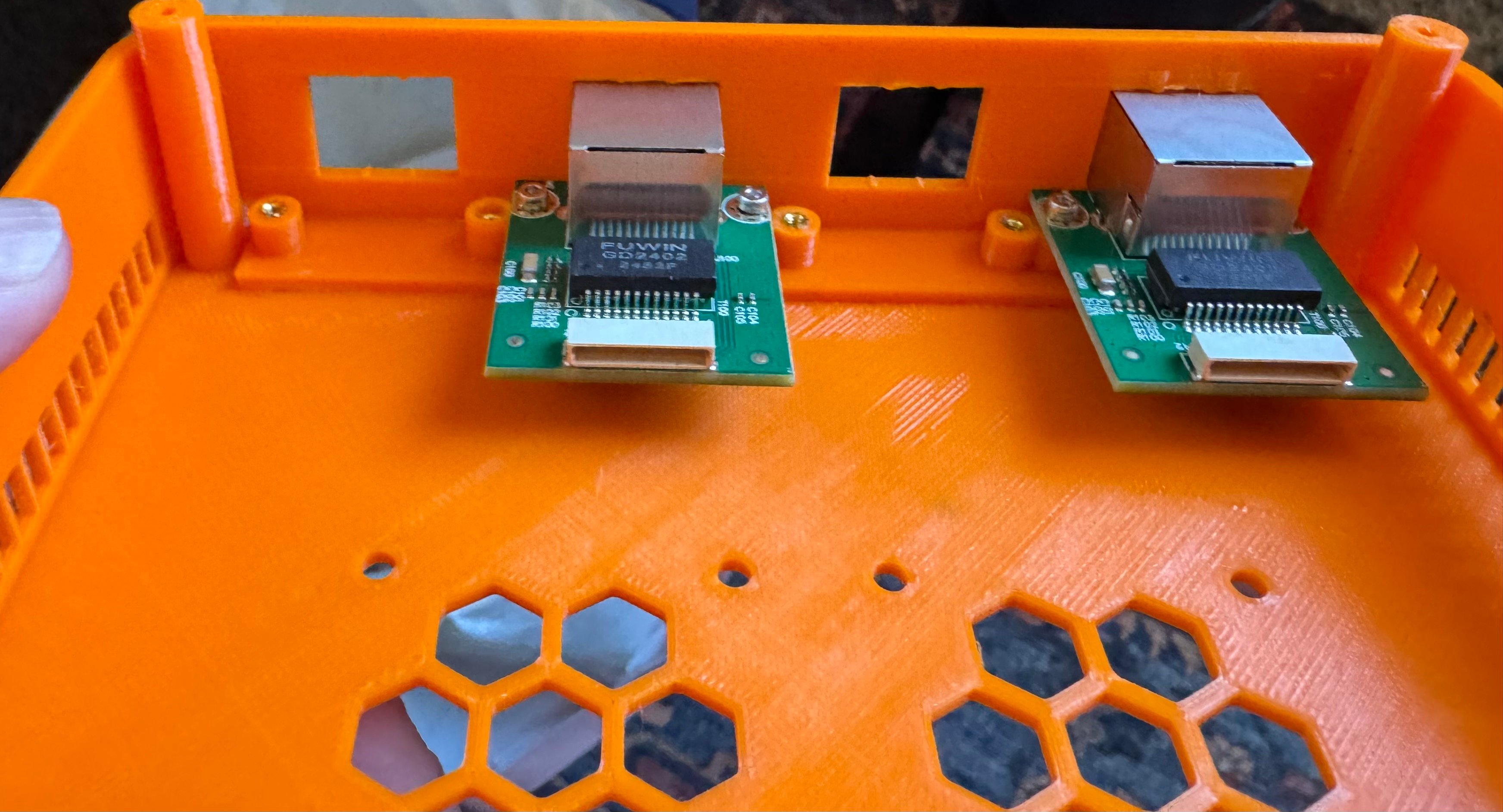
I installed the threaded inserts and then glued the mounting rail into place. I have a friend who’s a high school shop teacher and I traded him a computer for a literal lifetime supply of CA aka “Super” glue and activator. I find the industrial stuff just works better and is easier to apply than the tiny things you get at the store. The proof is in the pudding, I glued it into place without getting any on my hands! Glued into place, I screwed in the ethernet jack PCBs and was very satisfied to see them solidly in place.
The last tricky step was adapting the Noctua fans to the 4 pin SH1.0 JST connectors the stock fans use. I’m pretty slick with a soldering iron if I do say so myself, but soldering two bare wires together is still hard. I’d way rather solder a wire to a PCB than a wire to another wire. I even slightly tore down a Noctua fan to see if I could desolder the built in wires and solder the new connector directly to the PCB, but that’s not possible. In the end, I got it without too much trouble. I even verified the PWM and RPM sensors work. Technically you could get away with only using the 5V and GND pins, the fan would just run at full speed all the time, which for as quiet as the Noctua fans are, wouldn’t be a problem. I was just slightly mindful of the fact that running a fan at 100% all the time might reduce its lifespan from 100 years to only 50.
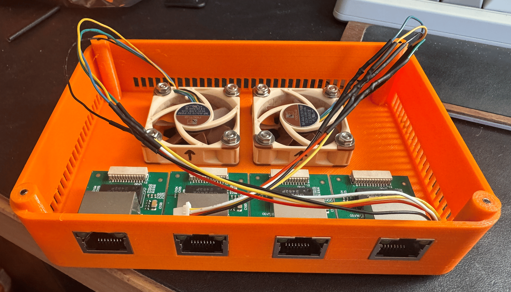
The NICs have a cable that connects from the m.2 PCB to the jack pcb and it was slightly challenging to get all the cables and fan wires coiled nicely in a way that wouldn’t interfere with the fans spinning, but I got it.
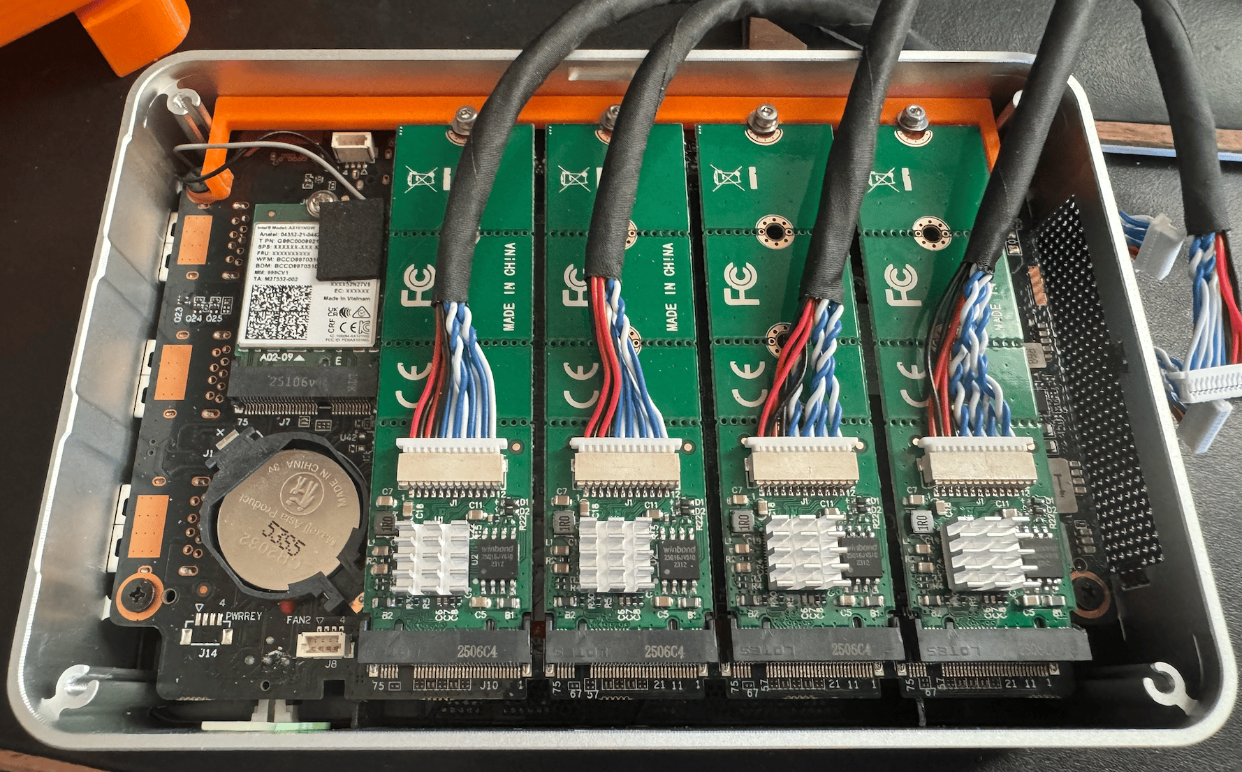
sleeeeeepy’s original design included some feet that would press fit into the screw holes on the bottom of the case to give some clearance for the fans to get fresh air. For my use case, I would be mounting the box on the wall of my network cabinet with some command strips, so I had Claude whip up two foot rails to give the fans plenty of room to breathe and accommodate the command strip. Once I had that in place, it was done!
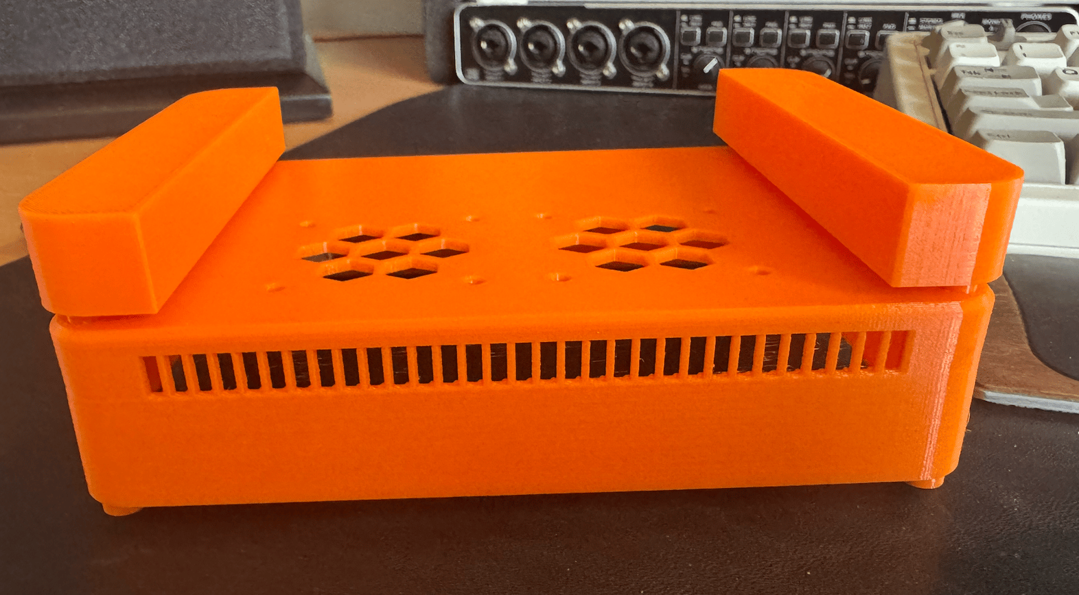
If you’re a maker too, you can probably imagine the sense of accomplishment of seeing a project you’ve been dreaming of for months come to fruition perfectly. It was clean. It’s still possible to take the whole thing apart. The hardware is all held in with screws, not glue. It’s also reversible, if I wanted to sell one of the NucBoxes I can reattach the stock bottom plate.
Software redundancy
My goal with the entire project was to have a hot spare ready to go in a moment’s notice. I want to be able to pull the WAN, LAN, and power cable from one box, put them in the new box, and be back up in less than a minute. I mulled over some possible options to keep a spare ready to go, or at the very least able to get ready as quickly as possible.
Initially, I had the live router backing up it’s config files to my NAS nightly. The plan would be to reflash fresh OpenWrt and then apply the configs to it. That was better than nothing, but still didn’t feel like it would be very fast in the case of an emergency such as the router dying in the middle of a work day. And now that I had an actual spare on hand, I could do a live test.
What I decided to do instead was have the live router do a complete backup of the filesystem with dd, then gzip it and store it on my NAS. Because OpenWrt only uses about 128MB of the disk space, and that 128MB compresses very nicely down to just about 17MB, this was a very reasonable option and also the most bullet proof. I have the script doing daily backups and I store daily backups for the past week, weekly backups for the last month, and monthly backups for the last year. I also have the backup folder rsync’ed to some off site storage as well.
From there, I installed Alpine onto a thumb drive and set up a script that auto runs on boot that will pull the latest backup from the NAS and flash it to the internal eMMC drive. This whole process takes about 2 minutes from cold boot into Alpine to cold boot into the freshly backed up OpenWrt. The BIOS will boot from the USB drive first, so any time it boots it clones itself to the live router. Then if I need to swap boxes, I just pull the USB drive out and it’s ready to go.
There’s a small detail I’ll skip over in order to make sure the WAN port is always the same physical jack location on the hardware. In Linux, interface names (eth0) are assigned in the order the interface is detected, so they’re generally stable on the same system but not necessarily deterministic between OS installs and hardware. There’s a small OpenWrt boot script that assigns WAN to one of two MAC addresses (one for each box). The other interfaces are all LAN.
Closing thoughts
It’s been a fun project to work on. For whatever reason, having a rock solid home network is just a hobby I find interesting. When I work from home, stable internet is as much a part of my livelihood as my ability to see and type. I’ll sleep just a little bit better knowing I have a great disaster recovery plan if my cool little x86 OpenWrt router ever bites the dust.
If I did it again, I might consider using the one m.2 slot in the NucBox that is able to take an m.2 SATA SSD as the boot drive and removing the built in m.2 A+E key WiFi card and putting 3x B+M key NICs and one A+E NIC. I’m a little torn there, since the ability to use the NucBox to also broadcast a WiFi network or possibly connect to a mobile hotspot for WAN failover is mildly appealing.
If you want to try this yourself, you can find the files and bill of materials on the Printables page↗.
-
Except the one time after an OpenWrt upgrade when the WAN only negotiated 100MbE on reboot and I didn’t notice for a week. Restarting the interface solved the issue. ↩